Minolta 5600HS(D) - Inside
In order to find out more about the power supply for the 5600HS(D) flash unit,
I decided to take a look inside the body of the flash unit.
For the ones with a weak heart, there are also some nice photos.
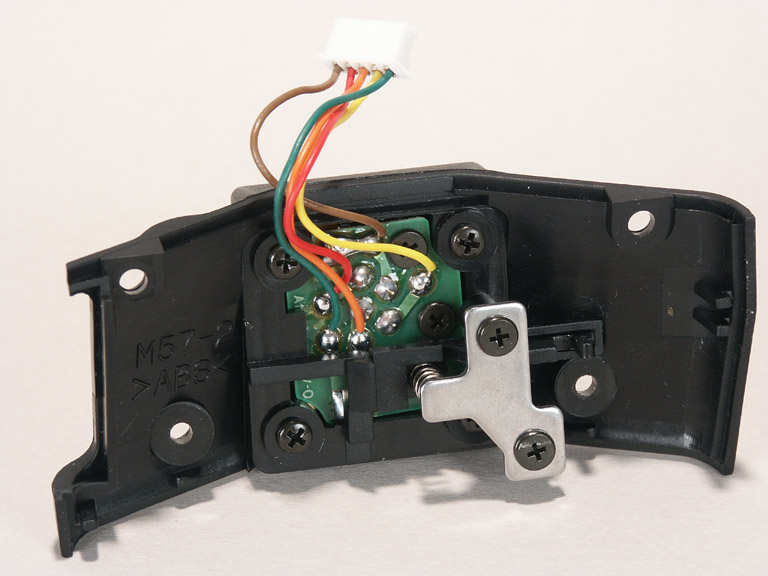
The foot plate, 5 wires: 4 sync pins and the switch.
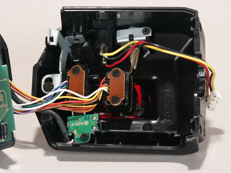
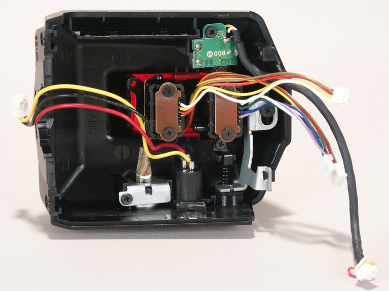
The middle and back part, foot plate and external power disconnected.
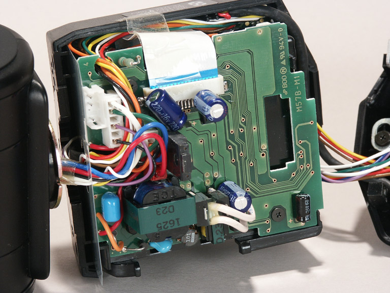
The front part, external power already disconnected from the power PCB.
The back part, foot plate and PCB disconnected.
The front part with the external power connector (bottom right).
The red wire is connected to the side pin with the plastic tip,
the black wire is connected to the middle pin and
the yellow wire is connected to the full-metal side pin.
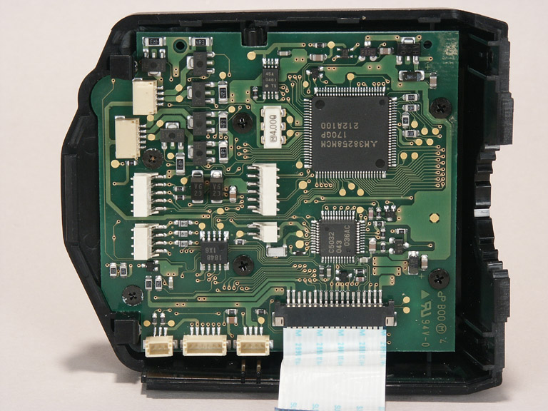
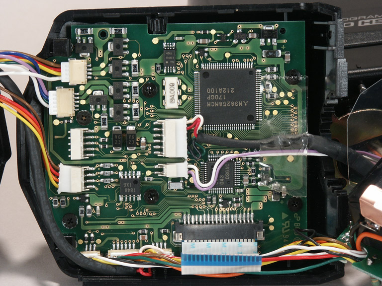
The back part with the microcontroller PCB.
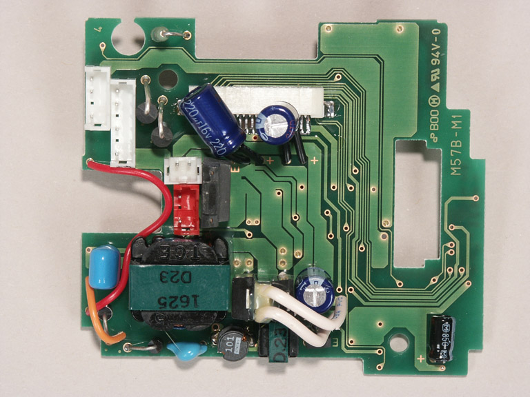
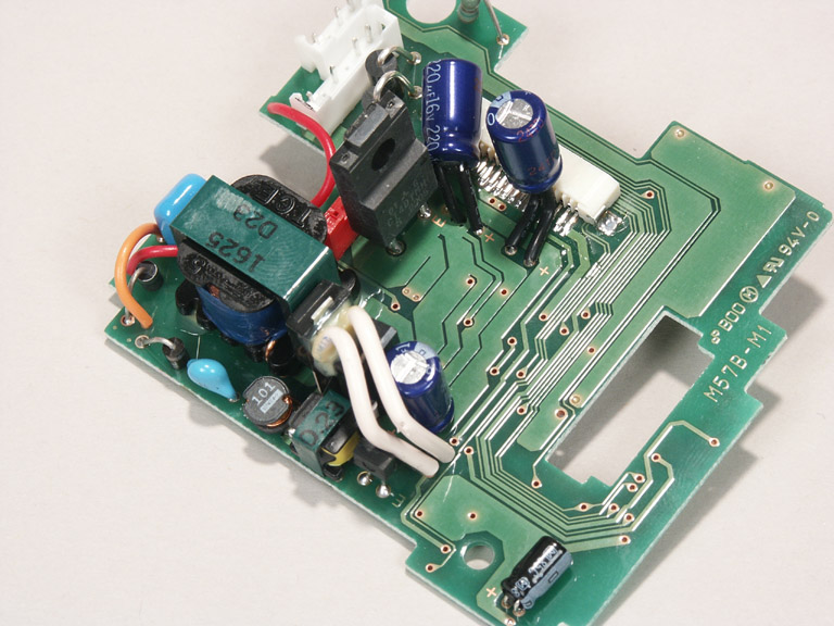
The power supply PCB, top view.
The white two-pin connector is the internal power input, left: orange (+), right: black (-).
The white four-pin connector on the top left is the external power input, top: yellow, middle: black, bottom: red.
The wires from the red connector lead to the head (top: blue, bottom: red).
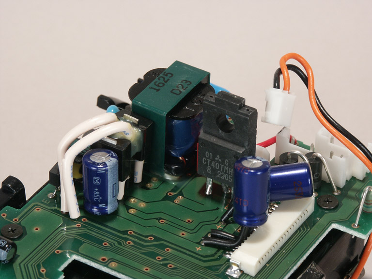
The power supply PCB, main corner.
The power supply PCB, another view.
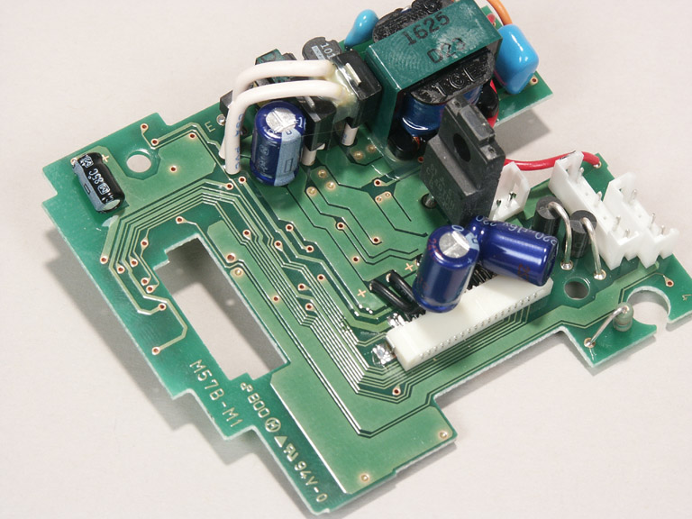
The power supply PCB, yet another view.
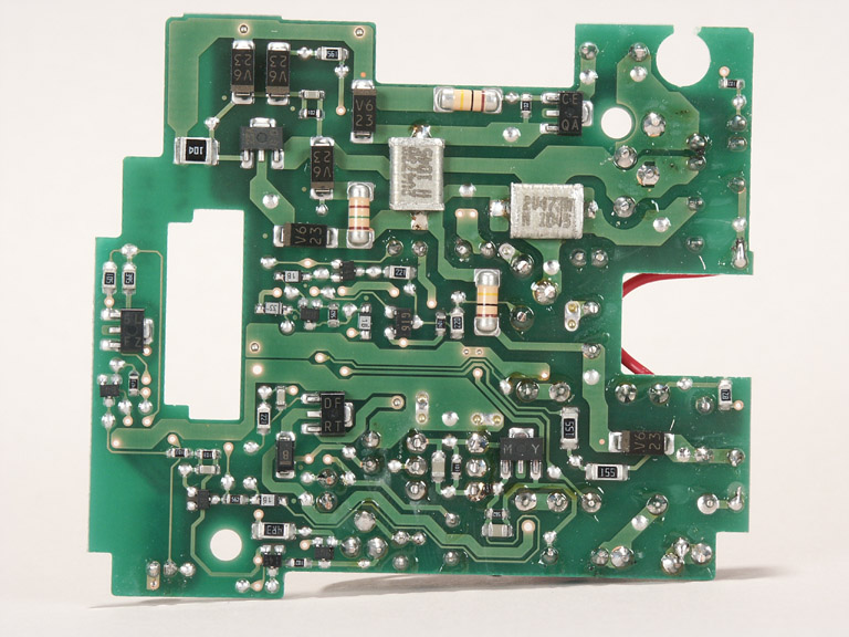
The power supply PCB, bottom view.
This is really lousy soldering work with lots of colophonium residue.
I couldn't do it worse.